To Infinity, and Not a Parsec Beyond

I have been quite active on the Black Widow Cosplay Community on Facebook. I liked the new eskrima stick weapons introduced for Black Widow for Infinity War and when Vanity Fair published some high quality still photographs of the new costume and props, I started working on an Infinity War version of Black Widow.

I’m probably not going to write blog posts on how I made the costume, but I think it makes sense for me to post links to my MyMinifactory profile page, where you will find STL files for 3D printing many of the required props for that costume: https://www.myminifactory.com/users/jmunkki

As of this writing, you can find models for the sticks, the backpack, the widow bite wrists, the shoulder, elbow and knee pads and some models for the tactical belt.

Also, a South African web site asked me to write about some of the designs and they published an article on these props, which you can find here: https://www.htxt.co.za/2018/05/11/black-windows-infinity-war-weapons-brought-to-life-with-arduino/

Black Widow, Part 10: Interlude

Status Update

I planned the original series to have 10 parts and hoped that this tenth part would largely based on any feedback and question I got from people reading the first nine articles. So far though, there haven’t been any questions and relatively little feedback.

I’ll just give a quick overview of where I have been and what I have been doing cosplay-wise and follow up with some more detailed articles later on.

January

Right after New Year, the capital area cosplay organization held a dance ball very close to where I live. A friend of mine was going there and had an extra ticket, so I went along with her. The reception to my costume was hugely positive even though it wasn’t much of a dance ball costume. The party also included a visitor vote for queen & king of the ball and I was hugely surprised that I was voted queen. It was truly an honor to be chosen. At the moment, the event page still has a photo of the crowning, but I think it’s just the header image for the organization. The venue also posted some photos here and on Flickr (I don’t think I’m in any of the Flickr photos). Finally, there are some studio shots here.

So next year I will hopefully be going back to the cosplay ball to crown my follower. I have an idea for a new costume that should be more befitting the occasion… The prize also included a VIP entry ticket to the Cosvision convention in April.

As you could see from the previous post, I created a new version of the Widow’s Bites using 3D printing. Part of the idea was to get them to light up a bit brighter, but in hindsight, that would require two LEDs per pod, so the end result wasn’t much brighter than the original. However, the new ones do look a bit better than the first ones I made. I’m slightly tempted to make a third version, 3D-modeling the pods using Fusion 360 rather than Blender, doubling the number of LEDs and adding transistors to drive them much brighter. Using CR2032s wouldn’t be practical with that version.

February

In February, I did a road trip along the California/Oregon coastline and found myself in Portland just in time for Wizard World. I was rather tired on Friday and had a tight schedule on Sunday, so my cosplay was limited to Saturday. I had a good time and enjoyed the panels. There’s a couple of photos of me on S. Shadow’s Natural Photography gallery on Facebook (thank you!).

While I was in the United States, I also picked up my Mood Fabrics order for spacer mesh and brought it with me back to Finland. I managed to sew a new suit around Easter time. I’ll write a full post about the suit later on…

March & April

The new suit was ready about two weeks before CosVision, so that left me with time to work on some other things as well. The guard belt I had ordered from eBay never arrived, so for Portland, I just made something quick to use with the Cobra buckle. For Cosvision, I had enough time to buy a new belt from Ebay.

The two weeks after I had completed the suit were also enough to put my full attention on making new utility belt pouches. The original 3D-printed ones were just props that didn’t do anything interesting and that I had modeled in Blender as my learning project. The new version pushed me to become much better at using Fusion 360 and I’m really happy with how it turned out. Even though I had a clear specification of what the end result should look like, it still left me a lot of work in terms of making a design that functions and prints well. The new version is printed in five different pieces and includes some simple electronics. The discs have a reed (magnetic) switch that lights up a blue & red LED inside the disc if you pull them out from the pouch. The design looks very close to the Avengers utility pouches even though I left out a little bit of fine detail that just didn’t print very cleanly and caused some 3D-modeling headaches as well. The utility pouches would be a good topic for another blog post… 😉

I’ll write about Cosvision & other stuff in another post, but here’s one of the photos my friend took of me while I was there.

Cosvision 2016 Black Widow

Practically every piece of the costume upgraded since Halloween… Best of all, this is the suit I made.

3D Printing

Aside from tailoring the suit, most of my spare time has gone into 3D-printing related activities. Upgrading bits of the costume is a good excuse for firing up Fusion 360 and making something interesting. I have a new version of the logo buckle that actually is a functional belt buckle and will probably upgrade it further so that the black center part works as a release button (no promises though). I now have two 3D printers. In addition to the Wanhao i3, which I have been upgrading & tinkering with, I also bought a Fabrikator Mini from Hobbyking. I think I’ll write a separate article on my thoughts on these printers and possibilities of using low cost 3D-printers for making cosplay props.

I have also used 3D-printing to make molds for Smooth-On Dragon Skin silicone. I have silicone-cast SHIELD patches, but I didn’t buy any psycho paint, so I haven’t tried coloring them, so I’m still using the patches I made in December. The silicone was actually for something much bigger and it took a few tries, but I managed to get a finished product. Maybe more on that in a later post…maybe…

Power Converters from Tosche Station

This isn’t the part 10 that you weren’t looking for… This is just a “work in progress” type of blog post.

As I mentioned in passing, I recently bought my own 3D printer. I started working on a 3D-printer version of the Widow’s Bites and the model looks a lot better than the shrink tube version in my old ones. The windows are a bit smaller, so lighting them up evenly and brightly is even more difficult than with the old version though. Despite the difficulties, I still seem to be pushing on to finish the new version.

CR2032 batteries are OK for the bracers and knowing that I get over 10 hours with the old design, I can probably make a slightly brighter version and still get OK battery life. I tested a breadboard version with blue and white LEDs and the 3.3V trinket and also powered it up with a Hubsan LiPo battery pack. 500mAh would be a huge upgrade. It worked great. I want something I can travel with though and airline regulations are getting tighter and tighter. Even tiny LiPo battery packs might just be too much.

However, I realised that the 3.3V Trinket is perfectly happy with a 6V supply. In fact, the BAT connector is both reverse-polarity protected (no worries if you connect the batteries backwards) and it takes up to 16V and regulates it down to 3.3V. Going with the 3.3V trinket this time just changes the resistor values and allows me to the LiPo packs when it’s convenient and CR2032 when they are more convenient. Best of both worlds…

3D-printed Widow's Bite module mounted on the breadboard prototype.

3D-printed Widow’s Bite module mounted on the breadboard prototype.

Black Widow, Part 9: Hair Me Now

Confession time: I have a bit of a wig collection. One of the reasons I started working on the Natasha Romanoff cosplay was that I knew I had an old wig that was close in style and color to her hair in Avengers and Avengers: Age of Ultron. Maybe a tiny bit shorter and fluffier, but still a lot better than the average costume wig for Black Widow. I had about two weeks to prepare for my little cosplay presentation, so I wanted to keep the costume really simple and base it on items that I already had. I had the brown leather jacket from Captain America: The Winter Soldier and I had quickly made the arrow necklace for that costume. Her hair in that film is still about the same color, but it’s straight, so I had a bit of a olloilemma there, if I wanted to be accurate.

Ideally, I wanted an inexpensive wig in the right style and color, preferably with front lace. I had never bought anything from Aliexpress, but I found something fairly reasonably priced there and decided to try to get it quickly by paying for express shipping. The item page said the wigs were in stock and available in a day or two. Thing is though, some of the vendors on Aliexpress are not trustworthy…some of them aren’t even there. What happened was that the vendor didn’t seem interested in fulfilling my order and Aliexpress just refunded my money after about two weeks. I got a free lesson and if I ever decide I want to buy anything there again, I’ll make sure to have low expectations and to be very careful checking the recent sales history of the vendor.

Meanwhile, I ordered a cheap Winter Soldier style Black Widow wig from Ebay. It didn’t arrive in time for the presentation and while it was an OK wig for the price (about 14€ including shipping), the color wasn’t quite the right. The wig was quite heavy (thick fibers and way too much hair too), making it feel somewhat unnatural and difficult to keep off the face. Somehow it often reminds me of Cousin It. For the presentation, I used the old wig.

The Right Color

Wig colors are described using code numbers. The numbers vary a little bit depending on where the fiber is from, but they give a reasonably good idea of the color. Unfortunately color isn’t as simple as just one number. If you have ever shopped for wigs online, you’ll know that the sample photos and hair color swatches on websites can be really inaccurate. This link is to a chart where the reds look pretty accurate to me. Most wigs feature more than just one fiber color. They might be frosted, tipped, rooted, ombré, etc…

For the Natasha Romanoff in Avengers, the closest single color on the wig charts is probably 130 (a copper red) or a 28 (golden red). Single color wigs generally do not look all that great, so in this case, I would probably try to get a fairly classic mix of 33 and 130, which will usually be called 33/130. The Winter Soldier style wig that I got from eBay was actually a 27, and a 27 with no highlights or other colors added tends to look a bit dull – it’s a light auburn or strawberry blond and not a rich auburn like it really should be for agent Romanoff. So while 27 isn’t exactly right, it’s not entirely wrong either and it can work in combination with slightly richer/darker reds. The old wig that I already had is a 32D and it’s is another light auburn and it’s pretty close, but maybe a tiny bit too light – possibly because that wig has some highlights too. 33 on the other hand is a dark auburn and it’s too dark on its own for the Avengers look. For the Iron Man 2 look, I would definitely want something with 33 in it, combined with something a bit “browner”. 33/32C from Revlon and Dark Red from Envy are both extremely beautiful colors, but probably darker and deeper than the hair in Avengers.

Color depends a lot on lighting. If you take a random reference photo of Scarlett Johansson in Avengers, the hair could look anything from brown to burgundy to light auburn. In addition to the light, there’s a ton of processing done on the image as well before you get to see it.

Style Matters Too

Costume wigs are inexpensive, but they generally do not look very convincing. As far as I know, Scarlett Johansson was wearing a wig for Winter Soldier and is wearing one in Civil War. High end wigs can look absolutely like real hair, but they are expensive. For an anime/manga cosplay, I think it makes sense for the hair to look fake, as long as it looks fake in the right way, if you know what I mean. For a cosplay based on an actual person (actress in a film), I think it’s better if the wig looks at least a bit like real hair.

There’s an interesting divide between wigs made primarily for white women suffering from hair loss (often because of chemotherapy or alopecia) and wigs made for African American women. Synthetic wigs of the former type typically cost between $100 to $400 whereas African American wig brands (like Freetress) tend to sell for between $20 to $80. The styles are different and the African American wigs are much more likely to come in more extreme color blends – I think they are marketed as fashion items and thus priced accordingly.

I wasn’t 100% happy with the Dolly Parton Daydream wig I already had – it was close, but not perfect. So while I was on a business trip and couldn’t work on crafting anything for the costume, I spent some of my free time to look for better options. I saw a Freetress Channing in a wig shop and it looked promising, so I looked at some other Freetress wigs and found Tammi and Sammi. These are all very affordable lace front wigs and I think the Sammi in particular is a pretty good style match for the Avengers Black Widow. Unfortunately the color range is a restricted and most of the colors are “ombré”, because it’s so fashionable right now. I had to choose between OP27 (near black roots and not red enough) and 530 (a near-burgundy red, but a solid color). The color is a burgundy red, which makes it darker and more blue-toned than I would like, but the style is nice and reminds me of the first BW scene in Avengers where she is tied up to a chair. The color is closer to the hair color in Iron Man 2. It’s Futura fiber, so it can be styled with heat. I tweaked the part a little bit and tried to mess with the curl a bit too, but I’m not sure I changed it all that much.

Freetress Sammi is the wig I used for Halloween. I tried the old Dolly Parton and the Sammi with the costume and the Sammi immediately felt like the better choice. It got quite a few compliments too.

Some time after Halloween, I bought the Envy Brittaney wig in dark red. It’s a new wig introduced for fall 2015 and it has apparently been super popular. I bought the dark red color because darker colors tend to look better on me. It’s quite possible that the lighter red would have been a better match. The wig is a bit lot longer than what you would want for Black Widow in Avengers or A-AoU, but I did a quick photosession last night with the full costume and trying on various wigs and found that the Brittaney was only slightly too long and actually looked great. For now, that’s my best wig for Natasha now. It looks natural and the color is nice.

I’m focusing on the first Avengers film costume & look, so I’m still kind of hunting for a great wig. There’s a customized lace front wig available on Etsy, but I’m not quite sold on it. The style seems very similar to the Sammi, but the color is probably more accurate. Having discovered how well the Brittaney works for me, I think I’m OK for a bit now. Having someone cut the Brittaney a tiny bit shorter is also an option.

Captain America: Civil War

Based on the trailer and photos, Black Widow’s hair is longer again in Civil War and it’s a more brownish red than before. Just last summer, I bought a wig that seems extremely close to the Civil War style: Christie Brinkley’s Editor’s Choice. I have the HT3025S+, which is what was used in the brochure photoshoot for that wig. It is a red color, but it’s fairly subtle. The HT3329S+ would be a more pronounced red (probably a good color choice for Avengers & AoU). The HT829S+ could also be a good color to match Civil War. The color codes may look a bit odd, but I think they can be broken down to 30/25, 33/29 and 8/29 fiber combinations. It’s a very natural-looking wig. Comparing with the trailer footage, Editor’s Choice probably isn’t quite as full-bodied as the wig that Scarlett Johansson is wearing for Civil War. The curls are very similar (+you could add more because the wig is heat-friendly) and the length looks about right too.

One thing to note about the photos of the wigs on the wig head is that the wig head is a bit on the small side, so the wigs look a little bit longer on it. For example the Dolly Parton Daydream looks like like the right length and the Envy Brittaney looks way too long, but in reality the Daydream is slightly short and the Brittaney is only slightly too long. I felt I could do a better job comparing the wigs by photographing them on something neutral, using a flash. In dim indoor lighting conditions the colors do not look this vivid.

Makeup

You can find Black Widow makeup (Scarlett Johansson style) tutorials on Youtube. It’s a relatively easy makeup to do, although most people do not have Scarlett’s pouty lips, so the lips are probably the trickiest part.

The usual concealer, base and powder go on first. I use Kryolan liquid concealer, Max Factor Panstick makeup and a Mary Kay loose powder + a Maybelline powder compact for a few spots. For eye makeup, I use golden brown tones with lighter color on the inside and darker shading near the outer corners. I apply a black eyeshadow with a 00-sized artist brush by dipping the brush in water and using the eyeshadow as a sort of watercolor. The lower lid just gets a bit of kohl pencil on the surface above the lashes. I think I’m still not using enough brow pencil on the eyebrows – at least in photos is looks like the brows could be even more sharply defined. Mascara is important, but I have been skipping the eyelash curler just to be a bit faster with the makeup.

On the lips, I use a relatively neutral lip liner to line the lips well outside their natural line, especially on the upper lip. I then use two different pink lipsticks on top of that. A bit of blush and I’m done. No contouring or other fancy stuff, although I bet a makeup pro would do a far better job than I can (and I think Scarlett Johansson has one available for the films).

Part 10?

I have an outline for part 10, but it’s not a complete article yet. I was hoping to get comments or feedback on the articles posted so far, but I guess I haven’t found an audience quite yet. So, there might be a part 10 in the future and then more updates, but this is the last pre-written blog article that was posted on the hectic 4 articles per week schedule. I received fabric samples this week and patterns recently and I also bought a basic 3D printer, so I haven’t been idle.

If you have been reading & enjoying these articles, thank you for reading!

Black Widow, Part 8: Control Software

Ghost in the Shell

In this third part of the Widow’s Bite build, I’ll explain how the software that I wrote works. I’m an experienced software engineer – it’s what I do for a living. With that in mind, it’s possible that even though I will try to keep this article simple, some if it may be difficult to understand unless you already know programming. Fortunately, once the bracers are built and since the software for them already exists, all you need to do is figure out how to install and configure the Arduino development kit on a computer, configure the plug-ins for the Trinket and then load up the code on the Trinket. Arduino is really popular, so the IDE will work with MacOS, Window and Linux.

Without software, this is all the bracer would do...

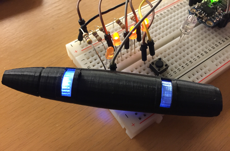
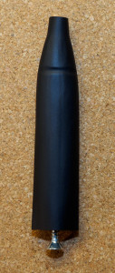
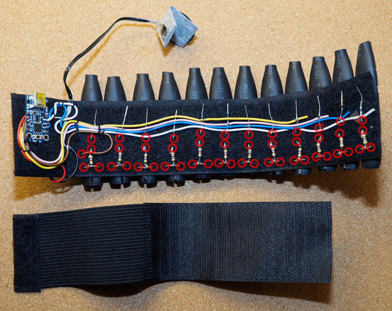
Without software, this is all the bracer would do…

Here’s a link to the source code. If anyone is interested in collaborating & developing this further, I could put this on Github. Let me know!

Stunning Bracelets and How to Use Them

Once the Widow’s Bite has booted up, it does a short startup animation and then goes into a background animation mode. The bracer just shows that animation endlessly until you tell it to do something else or you turn it off. It’s always running either a background loop or a triggered action sequence. Starting an action will suspend the current background loop, then run through the action until it ends or until you trigger another action. When an action reaches the end of its animation sequence, the bracer will resume running the background animation where it left off.

Since we only have one button, we control the bracer using short and long presses and pauses, almost like using Morse code. The main difference between Morse code and the bracer is that the bracer will not wait for a pause to execute your action, so if you tap twice, the first tap will activate the action for one tap and then the second tap will replace that with the action for two taps. It’s pretty easy to add new commands and sequences by modifying the C program code, but here are the built-in ones as of this writing:

  • short: all LEDs flash briefly (great for throwing a punch)
  • short-short: all LEDs flash briefly followed by a spinning animation (double punch)
  • long: background animation 1 (mostly steady low brighness with periodic spinning animation)
  • long-short: background animation 2 (constant low brightness spinning animation that flashes and reverses direction periodically)
  • long-short-short: go dark (no animation, LEDs are all off. Don’t mistake this for turning off the bracer, because the Trinket is still on and uses power)
  • long-long: background animation 3 (LEDs on at low brightness, but with a constantly rotating light that flashes bright and then turns off briefly)
  • long-long-short: activate normal power/dim mode (one LED group is bright, 3 others off for 2 seconds to indicate low power)
  • long-long-long: activate high power/bright mode (one LED is off, 3 others are full brightness for 2 seconds to indicate high brightness)

After the brighness changes, the default background mode is activated automatically. The maximum brightness isn’t affected by the mode change at all, but anything dimmer than that is affect. Essentially, the LEDs switch between gamma curve 1.6 (normal) and 1.2 (bright), if you are familiar with display gamma curves.

The Code

The software consists of four functional modules. I wanted an easy and compact way to animate the LEDs. I also wanted to be able to control the brightness of each LED group. Due to the limitations of the Adafruit Trinket (5 GPIO pins), each output pin controls three LEDs. Essentially, we just have four pixels (picture elements) that repeat three times around the bracer. The Trinket has two “analog” outputs, but I wanted to have four, so instead of relying on the PWM functions on the Trinket, I wrote software that emulates that behavior on any of the GPIO pins.

Arduino is based on a simple idea where there’s an initialization call and then after that another function is called from a never-ending loop. Now imagine a card game and some people sitting at the table, playing cards. The card table is the device, the players are the functional modules and the loop function represents one round at the table where each player has their turn to play.

Pace It

In order to make the code easier to write, the first thing I wrote was a pace function. This module sets pace at which the loop function runs. Using the card game analogy, this player watches a clock and holds up the game until a certain time has run. If this was a real card game, each round might be set to last no less than 1 minute. After some experimentation, I set the loop to run once every 75 microseconds. That’s roughly 13000 times per second. The pace function is really simple, but it makes the LED brightness control function easier to write.

Tap recognizer

The next “player” at the table is responsible for checking the state of the glove switch that you use to control the bracer and translating your actions into commands that typically tell the bytecode module to start running a specific background or action animation. It recognizes sequences of short and long button presses and of course pauses between sequences. If you are adding new commands, find the switch(fullSequence) statement in the program and look at the code below that. The values for the case statements are octal numbers again, so they always start with a zero. Ones represent short presses and twos represent long presses. For example, case 0211: means that the code below it is run after you have performed a long press and two quick taps.

LED Control

The LEDs can only ever be on or off. In order for an LED to appear only half lit, the software needs to turn it on and off really quickly. Let’s say the heartbeat limits us to 1000 loops per second (easy round number for the sake of demonstration – it’s actually faster than that). The human eye starts to see flicker when a light is on or off for longer than about 1/25th of a second. Some people are more sensitive, so faster flickering is better… If the LED is on every even heartbeat and off every odd heartbeat, then the human eye will receive about 50% of the amount of light that a constantly powered up LED would emit. Using the card game analogy, the LED control player lights up and turns off LEDs and then instantly lets the next player do something.

The brightness control system uses a kind of bucket or credit system for determining which LED should be on and when. Let’s say we only have two LEDs (or the others are simply off all the time) and we want them both to be at 50% duty. Each heartbeat, they bring 0.5 points to a shared pot and 0.5 is added to their “credit account”. Then, the controller looks to see if it has more than zero in the shared pot. If it has, it finds the first LED that has more than zero credit, turns it on for that heartbeat and then subtracts 1.0 from the pot and 1.0 from the credit of the LED that will be lit for one heartbeat. The lit LED now stands at -0.5 credits. The pot has zero credits left, so the controller has spent all it’s budget and just turns off any remaining LEDs. The next round, the pot goes to 1.0 again and the credit of the first LED is zero, but the second one is at 1.0, so the second one gets its turn and now we’re back to where we started.

Instead of values from zero to one, I’m using 10 bit fixed point, so a fully lit LED is at 1024 and a fully turned off LED is at 0.

Another thing that the LED control function does is to map from “virtual” LED numbers (in our case 0-3) to actual I/O pins. Because I wired the left and right bracers using different GPIO pins, the mapping is slightly different. From the animation software point of view though, it just controls LED groups 0-3 and doesn’t care what GPIO pin is used.

As a side effect of how the LED control function was written, it also controls the LEDs so that the maximum amount of current used is as low as possible. In the example above, only one LED at a time is on at a given time, so the two LEDs are using the same amount of energy as if we had one LED on all the time. If we just used a dumb PWM, it would likely have both LEDs on at the same time and then both off. The coin batteries we use aren’t particular great for high current  draw, so it makes sense to try to use an even trickle of current rather than a spiky mess that constantly alternates between zero and max.

Bytecode

The bytecode interpreter is much like a simple microprocessor even though it’s not a general purpose CPU. It has a program counter and some registers and stacks of sorts. The animations are stored as arrays of bytes in program memory on the Trinket, so I just declare a static “PROGMEM” array in the C code and use macros and octal numbers for the program. It looks a lot like assembly language and it’s a very efficient way to store animations. The interpreter is always either running a background animation or an action. If a background animation is running when an action starts running, the state of the background task is stored so that the animation can resume at the same point later on. I’ll give a brief overview of the instructions, as that’s most likely something that people will like to tinker with.

Using the card game analogy, this function reads instructions from a manual and does whatever the manual says. In this case, the bytecode program is the manual and the actions are opcodes.

LED Operations

The interpreter also simplifies brightness to just eight different levels (0-7) and uses a gamma table to translate to the low level 0-1024 fixed point brightness scale. When the level is zero, the LED isn’t lit at all and when it’s 7, it’s lit all the time (full brightness).

  • Single LED brightness can controlled with a three digit octal number where the first digit is always zero, the second digit is the number of the LED (0-3) and the third one is the brightness (0-7).
  • The opAll(n) macro allows you to quickly set the brightness of all your LEDs to n in one operation.
  • opClearAll is the same as opAll(0).

The opcodes just change the requested brightness for the LED. The actual GPIO port isn’t directly affected at all. Once the LED Control function runs again, it will turn LEDs and and off based on the requested brightness. This means it’s OK to combine an opAll macro with a code that changes just one or two LED values. Here’s an example:

opAll(1),
007,

Pausing

In order to actually see the animation, we can’t just change the lights infinitely fast and expect the changes to be visible. When a pause is encountered, the interpreter stops reading instructions until the required time has passed. Using the card player analogy, the pause opcode tells the player to pass all game actions until told otherwise or until a specific time has passed.

  • The opPauseTime(n) macro takes a number of milliseconds (n) from 0 to 1000 (1 second) and generates an instruction to pause for that long. I often use a #define macro to define a constant time delay, so that I can adjust the running speed of an animation simply by changing the number in the macro.
  • The opPause1Sec opcode just pauses for one second.

Here’s an example that also uses the previously shown LED commands:

opAll(1),
opPause1Sec,
002,
opPauseTime(200),
012,
opPauseTime(200),
022,
opPauseTime(200),
032,
opPauseTime(200),

Looping

Looping just means that the interpreter will repeat whatever is between the start and the end of a the loop a certain number of times, possibly infinitely. You can nest loops up to a few levels, but the stack only has 8 slots, which are shared by background and action animations, so you probably shouldn’t have more than 4 nested loops in any animation to be safe. Increase the stack size in the C code if you need more.

  • opStartLoop will start an infinite loop. You probably want one of these if you are writing a background animation as they should never end.
  • opRepeat(n) will start a counted loop where the loop is run ‘n’ times. For example, you might run an animation clockwise 4 times and then use another loop to run it counterclockwise 4 times before starting over again.
  • opEndLoop will decrement and check the loop counter and either pass through or go back to the start of  the loop depending on the counter. Note that this opcode will also cause the interpreter to yield control (effectively pause for the shortest possible time). The yield prevents your animation programming errors from making the bracer unresponsive.

Here’s a typical example (back_forth_speed is assumed to be defined a bit earlier):

 opRepeat(2),
 opPauseTime(back_forth_speed), opAll(0), 022,
 opPauseTime(back_forth_speed), opAll(0), 012,
 opPauseTime(back_forth_speed), opAll(0), 002,
 opPauseTime(back_forth_speed), opAll(0), 032,
 opEndLoop,

You can of course find many more examples in the tables within the C code.

Other Opcodes

  • You should have an opEndProgram opcode at the very end of each action. Background programs shouldn’t end, so if you use this opcode in a background animation, it will simply stop the program there. Action animations on the other hand will cause the previously running background animation to resume where it left off.
  • opNormalGamma switches to the default gamma table, which has better power conservation but slightly lower mid-range LED brightness.
  • opBrightGamma switches to the brighter gamma table, using a bit more power.
  • opToggleGamma switches between the two gamma tables (I ended up not using this, as it’s hard to keep track of what mode you are in).
  • opYield isn’t really useful. 🙂

Black Widow, Part 7: Epic Bracers

In this second article of the Widow’s Bite build, I’ll describe how the electronics were designed and built.

I used a 5V version of the Adafruit Trinket, which is a lightweight/low power version of the popular Arduino platform. The bracers can be built without the microcontroller, but adding the microcontroller only requires a few more wires and a tiny bit more soldering. The Trinkets are just ~$7 each and they open up a lot of possibilities, so there’s really no excuse to leave them out. If you build the circuit without a microcontroller, one adjustable resistor might be a good idea for controlling the brightness and power.

I built a mockup version of the circuit using just four LEDs and a 3.3V Trinket. The circuit is powered from the USB port on the Trinket. The 5V trinket will work too. I soldered headers on the Trinket to mount it on the breadboard, but it’s possible to do the mounting without soldering. The advantage of the mockup/test rig was that I could start working on the software several days before I had the bracer finished. The software is described in the next article.

Bracer circuit on a breadboard, using a 3.3V Trinket.

Bracer circuit on a breadboard, using a 3.3V Trinket.

LED Control Wiring

The outer bracer structure was shown in the previous article. To recap, the velcro has holes for the LED leads and holes for securing a ground wire near the back of the bracer. The photos show how the ground wires weaves through the velcro.

Completed Outer & Inner Bracer

Completed Outer & Inner Bracer

I pulled the LED wires through the holes in the velcro and bent the negative (shorter) lead towards the ground wire and the positive (longer) lead toward the front. I made small spirals on the resistors to make the soldering to the negative LED lead really easy (see part 5). To connect the other end of the resistor the the ground wire, I used a sharp knife to peel off some of the insulation on the wire and then pushed a sewing pin through the braid to make a hole large enough for the resistor lead. Doing this makes the soldering really easy.

Four control wires are used for the positive LED leads. Each wire is connected to three LEDs, so if you number the LEDs from 1-12, then the first wire will control LEDs 1, 5 and 9. The second one is 2-6-10, third is 3-7-11 and the last one is 4-8-12. There’s no way to control individual LEDs this way, but some nice animations are still possible even though you only have four pixels to work with. I used a black marker to mark the places where I needed to solder the LED wires and then peeled & made holes in the braid in those places. I used a sort of over/under weaving technique to secure the wires and LED leads. Soldering can be done as you do the weaving or it left until everything is in place.

I intentionally reversed the order of the groups for left and right so that if one side has an animation spinning clockwise, the other one would be going counter-clockwise. It’s a change that is actually very easy to do in software as well, so it doesn’t matter much which GPIO pins you pick if you know how change the program.

Glove switches

The Adafruit Trinket has five general purpose I/O pins. My design uses four of them for the LEDs, which leaves just one to use an an input to control the bracer. I took a low profile microswitch, a bit of bendable vinyl and some velcro to craft a switch that can be attached inside the palm of a glove. One wire connects to the ground and the other goes to the remaining I/O pin on the Trinket. There’s a square hole in the vinyl for the switch. Once the leads are soldered on, I used epoxy glue to fix the switch to the hole.

Power Supply

The power module is just a battery pack for two CR2032 lithium batteries. I like the battery pack because it has a built-in on/off switch and it’s really slim. I used some velcro stickers to attach it. The red wire solders into the BAT+ contact on the Trinket and the black wire goes into the ground wire, which is finally attached to the Trinket’s GND contact.

Battery life seems excellent, but if you want a rechargeable option, it’s possible to build the bracers using something a lithium polymer battery. Just be aware that you then need to use the 3.3V version of the trinket, the resistor values would need to be a whole lot lower and the LEDs must be verified to be close to 3.0V. There’s just 0.3V margin for the resistor to control the current, so in order to get 4mA per LED max, the resistance would be 0.3V/0.004A = 75Ω. For my build, I’m assuming a 6V power supply, which the 5V trinket regulates to 5.0V, so the resistors are 500Ω for 4mA per LED. I estimate battery life to be about 10-12 hours, but it will depend a lot on the brand of batteries used, the software loaded on the microcontroller and how much you run the LEDs at full brightness.

The Trinket will always draw 6mA of current, so even though you can turn off all the LEDs using a glove switch command, it’s a good idea to use the battery pack power switch when the bracer is not in use. Upon powering up, the Trinket will first try to connect with USB and because the I/O pins are shared between USB and our LEDs, this will cause some of the LEDs on the bracer to light up for a few seconds before our own software takes control.

Connect the Dots

The wires I used were all pre-cut and different colors, so the photos should make it pretty easy to see where they all go. I decided on where to place the Trinket and how to route the wires there. I then cut the wires to suitable lengths, tinned the leads and soldered them on to the Trinket. At this point, the bracer was ready for testing. As usual, there were moments of confusion and panic as nothing seemed to work. One of the batteries in the pack was dead. A new set of batteries helped a bit, but the bracer was unresponsive to the commands from the glove switch. At first I thought that maybe the coin batteries simply weren’t powerful enough for this, but plugging the bracer to USB didn’t help. I desoldered the button from GPIO 0 and moved it to GPIO 1 and that fixed the problem. GPIO 0 was working well as an output.

This is how the trinket is wired on one of my bracers.

This is how the trinket is wired on one of my bracers.

I decided to use the same design on both bracers…except that when I was soldering the second bracer, I accidentally used the orignal pin choices and ended up with another bracer with a dead palm switch. At this point, instead of just changing the wiring again, I tried to figure out why the switch didn’t work with GPIO 0. Soldering these leads the first time is easy…doing so the second time is harder – try to get them right the first time unless you have a good desoldering station. I guessed that it had to something to do with the red built-in LED on GPIO 0, so I just took a knife and cut it out. The switch started working. My first bracer uses GPIO 1 as the switch and the second one uses GPIO 0 and I need to make a tiny software configuration change based on which side I’m programming.

Due to voltage differences, GPIO 0 works great as the switch input using the 3.3V breadboard mockup, but not at all when conneted to the 5V version of the bracer. The red LED is actually very nice to have for debugging on the Trinket when you are programming it, but once it’s in the bracer, all it does is consume a lot of power. It’s just best to cut both LEDs off the Trinket. The built-in LEDs are surface mounted next to the USB connector.

I used needle and thread to secure all the wires and the trinket to the velcro. There are quite a few exposed contacts, so I think there’s a risk to create some shorts and drain the battery if you wear the outer bracer on bare skin. It’s best to always use the inner bracer with the bracer. The “pods” aren’t waterproof anyway, so it doesn’t seem worth insulating any of the other electronics either.

Wiring without annotations.

Wiring without annotations.

Black Widow, Part 6: Biting the Bullets

The Widow’s Bites are covered in three articles: physical prop, electronics and software.

The Widow’s Bites in the 2012 Avengers are relatively simple-looking bracers that use electricity to stun a target. If you look at the Chitauri fight scene footage, you can see some sort of stingers in the gloves that deliver the charge. However, these are absent in all the poster art that I’ve seen and I was using the posters as reference, so my design doesn’t incorporate the stingers. The modules/pods on the bracer are probably some kind of battery or capacitor that generates the discharge. When they are active, the two shiny bands on each pod light up in blue.

Each bracer I made consists of twelve pods. Most Black Widow costumes seem to make these pods either out of inexpensive costume shop bullet belts or mold them out of solid rubber/silicone. To be honest, I considered the costume shop bullets a last resort as I didn’t think they looked all that convincing. I spent a few days trying to figure out how to make the modules before I came up with an idea. I used heat shrink tube to make a hollow pod, so that I could actually build an LED or two inside and make it glow. I didn’t have a mold at that point, so I just took a bit of tube I had and shaped it using heat alone. It didn’t look exactly right, but it was definitely strong enough and looked quite promising already.

Sneak closeup preview of the assembled widow's bite bracer & glove.

Sneak closeup preview of the assembled widow’s bite bracer & glove.

Module Covers

I needed a mold inside the tube to get the right shape, so I took a piece of wood and started whittling. I wanted a tight fit over the 12mm diameter tube, so I was constantly checking the fit. The finished mold is 76mm x 31mm x 10 mm. There are twelve pods on each bracer, so I the minimum amount of shrink tube is nearly two meters with very little room for error. Since the tube is cheap, I recommend getting at least 4 meters. Speaking of cheap though, while the DX tube was great for this application, it does seem a tiny bit thinner than the stuff I have seen at local stores here. You could also buy tube that shrinks to an even smaller size to make the tips sharper.

After making one or two pods, I attached a small screw to the back of the wooden mold to make it easier to pull the tube off. Here’s how I mass-produced the pods:

  1. I cut the heat shrink tube into segments of the right size. The tube shrinks slightly length-wise, so it’s better to make the segments a bit long rather than too short.
  2. I inserted a tube on the mold and heated up the tip of the pod shape to shrink it down to size, making sure the groove became clearly visible.
  3. I then wiggled the mold out of the tube a tiny bit to make sure the front was loose and then pushed it back in again.
  4. Shrinking the back end of the tube over the pod makes it impossible to remove the tube without cutting it, so there’s a cut under each pod extending from the back of the pod towards the middle. This cut allows you to pull the tube off the mold and start with the next one.

It might actually be a good idea to add some indentations on the mold to show where the glowing windows on the pods should be cut, but I just cut them all manually using a reference pod that I cut.


The pod covers will shrink out of shape if heated, so they need to be kept safely stored away while working with a soldering iron or hot glue gun.

Internal Pod Structure

I spent quite some time experimenting with how to build the inside of the pod. The design I chose takes a bit of effort to build, but can essentially made from LEDs, cheap scrap material and clear tape. I used a sheet of translucent packing foam as the base, cutting it into strips that would easily fit inside the pod. The LED caps are pointing towards the tip with the positive (longer) lead in front. The longer leg is bent at a 90° angle quite close to the LED and the shorter leg a bit further away from the LED. The foam base helps prevent the contacts from shorting, but I also added a tiny bit of small diameter shrink tube to one leg on of each LED as insulation. Hot glue would probably work even better.

I used a rectangular piece of baking paper as a diffuser and on top of that, a similar size piece from an antistatic bag to give the pod windows a metallic blue color when the LED wasn’t lit up. Bits of clear tape hold everything in place around the foam and LED. It’s a good idea to test the LEDs with a resistor and power supply before soldering anything.

Outer Bracer

Instead of a circuit board, the LED modules are mounted on 5 cm wide loop (soft) side velcro. The pods are on the smooth side and the resistors, wires and CPU are on the fluffy side. I used a mini drill to make holes for the LED leads and to weave a ground wire near the back end of the velcro. I originally intended the battery pack to be hidden inside the bracer and while it is relatively flat, I ended up mounting the first set of pods slightly too tightly on the velcro. I guess I wasn’t accounting for all the layers between my bare wrist and the top velcro. In addition to the suit sleeve, there’s a hook side velcro as well. The battery pack actually looks like it belongs on the bracer and the slight discontinuity in the pods hasn’t bothered me at all.

Outer and inner bracers with red circles to indicate drilled holes.

Outer and inner bracers with red circles to indicate drilled holes.

The pods are held in place by the LED leads and a bit of heavy duty double sided tape at the front and back. The pod cover slit is taped up and the pods are taped in place as the very last thing of the build. You want to be able to slide the covers on and off easily while you are testing. Once everything works perfectly, you can lock them in place.

Inner Bracer

The inner band goes around the wrist and has some elastic for good fit & comfort. It consist of 12.5 cm (5″) of hook side velcro sewn onto 10 cm (4″) of elastic and 2cm (0.8″) of loop velcro.

Making 24 pods and wiring them all up takes quite a lot of time. It took me about three evenings to get the second bracer built from scratch. The first one took a lot longer, because I was spending more time designing and experimenting than actually building.

Completed Outer & Inner Bracer

Completed Outer & Inner Bracer

Parts:

  • 2 meters of Ø12mm heat shrink tube.
  • 24+ bright blue 3mm LEDs (3.0V – 3.2V, 20mA)
  • 24+ 500Ω resistors
  • A small sheet of translucent white foam
  • Some baking paper
  • A medium-sized antistatic bag or several small ones
  • Plenty of wire
  • 50 mm wide velcro (hook and loop) – one meter is probably enough
  • 50 mm wide elastic fabric band
  • two dual CR2032 battery holders
  • Two Adafruit Trinkets, 5V version
  • Two microswitches
  • Black velcro stickers
  • Solder & solder wick

Recommended tools:

  • Sewing machine
  • Soldering iron (15W sharp tip was great again)
  • Dremel-like drill or some other way to quickly make nice holes in velcro
  • Digital multimeter
  • Wire cutters
  • Wire peeling tool
  • Small pliers
Front view of completed bracer.

Front view of completed bracer.

Black Widow, Part 5: Not Lightsabers!

In this part, I’ll cover the baton weapons I made. Once I had the parts, these were very easy and quick to build. The second one only took about 2 hours and I definitely wasn’t trying to rush making it.

I’m not a Marvel lore expert by any means, but based on what appears in the films and what I have read somewhere, the batons were something that Tony Stark built for Natasha Romanoff some time after the Avengers and before Age of Ultron. I think the native Filipino term for them would be baston and the martial art they are typically used in would be eskrima, of which arnis is one sub-type (again, not an expert, so do your own research if you want to be sure). Whatever the case, those weapons look cool and at the same time lethal in the right hands. Check out this video on Youtube for basic instructions and a good show of high arnis skill. I made these for the Avengers (2012) costume because I wanted to focus less on the guns.

The versions I made look a lot like the Civil War concept art. I used mostly artwork based on Age of Ultron while planning it. My original plan was a bit more ambitious than what I ended up making: I wanted to have LEDs along the rod in the black segments and at the tip to make the light more even. This would have required some wiring and also structures to support the LEDs. I already had some clear/silver wire for it, but I decided to test a build with a small mirror at the tip and a flashlight like structure at the handle end. It worked beautifully, so I didn’t bother with the additional LEDs. I also considered embedding a microcontroller, but more on that later…

Ready for action!

Ready for action!

Components

The bastons I made weigh 175 grams each without batteries (almost exactly the same as an iPhone 6+), and 215 grams with a battery pack. Here’s what I used to make two of these:

  1. Two 500 mm (20″) “Perspex” plexiglass acrylic tubes. Inner diameter 26 mm (~1″), outer diameter 30 mm
  2. Two inexpensive 9 LED flashlights with AAA batteries in aluminum bodies
  3. About 3 champagne bottle corks (real cork)
  4. Two laser-cut round 25mm diameter mosaic mirrors from a local online crafts store
  5. Twelve bright blue LEDs, 3V, 20 mA (get some spares in case you lose or break some – I used clear cap blue LEDs from this box)
  6. Twelve 100Ω resistors (again, get some spares in case you break some)
  7. less than 1 meter of Ø35 heat shrink tube
  8. Solder and maybe some solder wick to clean up bad joints if you need to.
  9. Insulated wire
  10. Epoxy glue
  11. Plastic wrap like Saran wrap (I used a heavy duty version)

The plexiglass tubes cost about 32€ including precision-cutting to measure, shipping, and tax. The minimum order was two meters, so now I also have an extra 1 meter long segment that could be used to make two more baston or maybe a short-ish light sabre. The flashlights cost about 5€ each, so the total cost was well under 50€ (the Euro and USD are roughly equal at the moment, in case you are wondering).

Recommended Tools

  • Soldering iron (a cheap 15W with a sharp tip will work fine)
  • Digital multimeter (optional, but very useful)
  • Small Dremel-like drill and some drill bits
  • Small wire cutters
  • Sharp knife

I used the drill for one hole in each flashlight casing and some holes in the cork that holds the resistors and LEDs. If you don’t have a drill, I’m sure you can work around not having one. The negative pole of the flashlight battery pack is connected to the body of the flashlight. I stripped enough wire to make a loop around the threaded part of the flashlight that will go into the plexiglass tube. Feed the stripped wire from inside the flashlight to the outside and solder the loop so that it is secure. The other end of the wire will go through the cork, so make sure the wire is long enough for now and cut it to size once you know how much loose wire you need.

Remove the black O-ring and drill a hole under where it was for the negative lead.

Remove the black O-ring and drill a hole under where it was for the negative lead.

LED Module

I mounted the LEDs and resistors on and inside a piece of cork. I took a sharp knife and cut a segment from the cork that I then trimmed down to a size that would fit securely inside the plexiglass tube. Cut the cork to a length that allows at least the bulbous part of the resistor to fit inside. You can use any number of LEDs you like, but I chose to use six on each baston, so I made six holes in a circle directly through the cork and made sure they were just large enough to hold a resistor each. One more hole is needed for a negative lead from the flashlight body. The seventh hole is on the same circle as the LED/resistor mounting holes. I used a black marker to make sure I knew which hole was for that lead.

Note that one of the LED leads is longer than the other. The lead that has to plug to the positive lead from the power source is longer. This is easy to remember if you remember that the two lines that form a plus sign put together are longer than the single line in a minus sign. Each LED needs to be soldered to a resistor. Some cheap flashlights skip this and use just one resistor for a whole bunch of LEDs and they can usually get away with this, but if you are building something yourself, you might as well do it right? The LED will work with the resistor on either side, but for this particular build, you have to attach the resistor to the longer (positive) lead of the LED. This is because the negative lead from the power pack goes through the cork to the same side as the LEDs and the positive pushes against the base of the cork on the other side.

In order to pick a suitable resistance, you need to know the maximum voltage of your power source and the voltage drop across the LED. In my case, the maximum voltage from three AAA alkaline batteries can be up to 3 x 1.65V = 4.95V. The voltage will quickly drop to about 4.5V, but it’s better to design for the maximum. If I chose to use NiMH rechargeables only, I would calculate the resistor for 3 x 1.3 = 3.9V instead. The resistor is there in order to limit the current to the LED. If the resistor value is too low, the LED will burn brighter, but it might also burn out completely. If the resistance is higher, the LED will be dimmer and will use less power as well.

If you make a test circuit with a power source, some resistor (say 300-500Ω) and a 5V power supply, you can use a multimeter to measure the actual voltage across the LED. In my case, the voltage drop was 3.0V. The voltage drop across the resistor is 4.95V – 3.0V = 1.95V. Resistance is the voltage divided by the current. We want the current to be 20mA (0.02A), so the resistance is 1.95V / 0.02A = 97.5Ω, which is 100Ω when you round it up to a size that you can actually buy.

I came up with a little trick for soldering resistors to LEDs that makes the job a whole lot easier and doesn’t require super steady hands or special tools other than a pin or small paper clip. Starting from around the middle of the bare lead on one side of the resistor, wrap it tightly into a coil around the pin and then carefully bend it a bit so that the spiral is a natural extension of the resistor (see photo). Push the long (positive) lead from the LED through the coil and make a 90° bend on the short (negative) lead away from the positive lead. Use the soldering to apply a bit of solder on the spiral and you should have an extremely solid solder joint as a result. You can test the LEDs at this point by connecting them to a 5V power source – just remember to get the polarity right. Once you start soldering them all together, it’s harder to replace an individual broken LED.

The resistor goes in the tunnel through the cork and the negative lead points towards the circle of LEDs and meets the other negative leads right in the middle. Feel free to cut the negative lead to a suitable length or simply make another bend to form a neat little crown in the middle. The crown is where you also solder the wire that will be soldered to the body of the flashlight and that goes through the seventh hole in the cork.

First LED in place along with negative lead. Holes for 5 more LEDs.

First LED in place along with negative lead. Holes for 5 more LEDs.

On the hilt side of the cork, the lead from the resistor is also bent towards the center on that side. If the lead is really long and goes way past the middle, it can be trimmed a bit shorter than then pushed inside the cork with a 90° bend. Once all the positive leads from the resistors are neatly in the middle, apply a bit of solder to connect them all and make a small bump that acts as a contact point with the positive pole from the battery pack.

View from the battery compartment side, showing the leads from the LEDs meeting in the middle and the negative wire passing through the cork.

View from the battery compartment side, showing the leads from the LEDs meeting in the middle and the negative wire passing through the cork.

At this point, you can test the LEDs by pushing the cork against the flashlight body. Remember that the flashlight has a toggle switch at the butt, so you may have to turn that on if it was off.

Finishing Touches

The end cap at the tip of the weapon is also cork. I cut the cork to a size that makes a nice end cap and used double sided tape to attach the small mirror it. I added some epoxy later on when I had epoxy mixed to glue the hilt to the “blade”. I covered the plexiglass tube with a couple of layers of plastic wrap to make the surface look a bit more textured. I then cut three 7 cm segments (about 3″) of heat shrink tube and one 4 cm segment (1.6″). I perforated two of the longer segments a bit to decorate them a little. The two segments in the middle are not glued down, so they are easy to replace. (January 16th update: I ordered a 3D printer, so one application would be to make 3D-printed versions with detailed graphics.) Heat shrink tube is commonly used in electronics to insulate or wrap cables neatly. In this case, the rather large 35mm diameter tube fits nicely over the tube. I used an incandescent spotlight (60W, I think) to heat the tube, but you can use a hair dryer or the soldering iron or anything else that allows you to controllably warm the tube to over 125°C.

I mixed a bit of epoxy glue. The glue was first used to secure the mirror to the end cap and the end cap to the tube. Then, the LED module and the wire from the hilt to the module were glued in place. Last, the hilt and blade parts are glued together. They fit very neatly together and the threads on the flashlight ensure that the glue will hold really well. I then quickly applied the heat shrink tube over the tip and the joint between the hilt and blade. I used 5 minute epoxy, so all this needs to be done rather quickly. It’s probably better to work on one baston at a time.

AAA alkaline batteries have a typical capacity of 860-1200 mAh. Driving 6 LEDs at 20mA each is a total of 120mA, so battery life with alkalines is 7-10 hours of continuous use and that’s about how long my first set of batteries lasted. The LEDs will dim somewhat towards the end as the voltage drops and then at some point  they will not light up at all.

Batons with power off.

Batons with power off.

Batons with power on.

Batons with power on.

Even though this was a relatively simple and quick build, these props were very popular among my friends at the Halloween party. Possible improvements would be a brightness control and a sound output of some kind. The tube is large enough to fit an Adafruit trinket and the 3.3V version would work well with three batteries in the flashlight. Unlike with the Widow’s Bites though, I would probably prefer to drive the LEDs using transistors rather than directly from the microcontroller. This is because you want the weapon to glow rather brightly and the I/O ports only output up to 20mA per port.

Speaking of the Widow’s Bites: stay tuned for the next part of this series…

Halloween version of my costume. Flash photos tend to wash out the glow a lot unless you use a long exposure. This photo was taken without flash.

Halloween version of my costume. Flash photos tend to wash out the glow a lot unless a long exposure time is used. This photo was taken without flash.


Black Widow, Part 4: The Gunslinger

In this part, I’ll cover the guns, tactical belt, holsters and related items. I thought this part would be easy to write about, but because I didn’t put much effort into this part of the costume for Halloween, I did a lot of research while writing and upgraded pretty much everything in the process. I’m hoping this article didn’t suffer too much from the extensive editing.

Guns

In Avengers Natasha Romanoff is equipped with two Glock 26 guns. Most airsoft guns look very much like real guns and they are relatively inexpensive, but they can fire plastic pellets, so they usually need to be deactivated for conventions etc. I was going to use the costume at a night club and they wouldn’t allow a real-looking gun prop at the party, so I just made a quick foam & duct tape gun in half an hour before the party started. This was a big reason why I put much more effort into the Widow’s Bites and baton weapons – the gun that I had at the party just didn’t look all that great.

Glock has apparently been waging a bit of a war with replica makers, so I had difficulty finding an airsoft Glock 26. At least in Europe though, the Cyma P.698 is still widely available and luckily it’s dirt cheap too. I found some on amazon.de. It needs a bit of black paint to look right, but the shape and size are about right. I used heat shrink tubing to cover the orange tip, so if I need it to be orange, I just pull off the cap and it’s there. I also filled the barrel with epoxy glue. It’s a plastic barrel and a bit of testing revealed that the Cyma isn’t particularly accurate.

Aside from the foam gun I made for Halloween, I had an airsoft Walther P990 that I used as a part of a costume at a 007-themed party over ten years ago. I’m not much of a gun fanatic, but I can appreciate great industrial design when I see it and I think the P99 is a good example of that. The Halloween costume had just one holster and I used the P990 in photos that I took before the party.

Airsoft P990, quick & dirty foam gun and a pair of Cyma P.698 guns painted black.

Airsoft P990, quick & dirty foam gun and a pair of Cyma P.698 guns painted black.

Conventions and Rules

I’m going to go to Wizard World in Oregon in Februrary 2016 and possibly to London in late May. I found a nice, quick overview of US convention rules for weapon props on Youtube. The Cymas have been converted into convention-safe non-firing props, but making foam guns are also an option. I’ll travel through O’Hare airport, so I may also need to check to see if the extra strict rules in Chicago are a problem even when staying well outside of the city for a few days and keeping non-firing props packed up in my luggage. London shouldn’t be a problem.

Holsters

The drop leg gun holsters in the films are Blackhawk SERPA holsters. I couldn’t find a cheap SERPA holster for the P99, but DealExtreme had a H&K USP Compact holster for $15, so I took a chance and bought one. It was initially a very tight fit, but after the P990 had been in the holster for about an hour, it turned out to fit really well. I ended up buying a genuine left hand Blackhawk SERPA Sportster holster from Ebay. I didn’t actually notice that the DX holster was for the USP Compact than until the genuine on arrived. There are definite differences in the design, but both holsters work well with the Walther and the Cymas.

H&K USP Holsters work well enough for Cosplay

H&K USP Holsters work well enough for Cosplay

You can save a bit of money and trouble by going for an Age of Ultron configuration where she only has the left side holster and one gun.

There was one extremely entertaining puzzle related to the holsters though. The DX holster camewith two different mounting platforms. One of them is a rounded paddle that slots at the top of your pants and the other one is a belt loop platform. For the costume though, you want to drop the holster down to the leg. You can get drop leg versions of the Blackhawk SERPAs, but they are a little bit more expensive. I spent probably two hours just trying to get the standard platforms securely mounted down on the leg, but the gun was just top heavy and wouldn’t stay nice and flat. Then I came up with a crazy idea and it turned out it worked perfectly.

The idea was to ignore the third mounting screw completely and flip the belt loop platform upside down. That way it is mounted much closer to the pistol grip. Also, the slot where the third screw went is now all the way up and is perfect for attaching the straps that comes down from the belt. Obviously this isn’t the way you are supposed to use the mounting platform and you are ignoring one screw, so there’s no guarantee this would be a safe configuration for a real gun. For cosplay with props, it’s fine. Note that the Blackhawk Sportster holster only comes with the paddle platform and it’s a dark gray rather than a black. I used just a bit of matte black spray paint on it and found a belt loop platform for $6 on Ebay.

Upside down belt loops used as drop leg platforms.

Upside down belt loops used as drop leg platforms.

I took belts and buckles from two worn down waist packs. The straps are heavy duty cotton, so they look nice and didn’t cost a thing. In the Halloween costume, both straps as used for the single holster, but converting the costume to double holsters, I made new straps to go around the legs and used 2cm elastic for them. I think the holster is much more likely to slip a bit if the straps do not stretch at all.

I have seen photos of many Black Widow costumes that use the velcro/cordura cloth holsters. I bought one from DealExtreme for about $10 just to make sure I had at least some kind of holster in time for Halloween. In terms of holding any type of gun and maybe a bit of lipstick etc, there’s nothing wrong with them, but be aware that they are far bulkier than the SERPAs. In terms of looks, the SERPA wins hands down.

Belt & Buckles

I bought a guard belt from a local military supply store. One thing to note is that tactical belts have a velcro surface on the inside and part of it is left uncovered. The belt that I got has the hook side, so in order to reduce wear on the suit under it, I bought some more 5cm wide velcro and used it to cover the rough part. If you want the belt to stay exactly in place without slipping at all, you could sew the inner velcro to your suit. I can see how that might be necessary for actual combat duty and when you have some more weight attached to the belt. The belt buckle in the Avengers movie is an AustriAlpin Cobra. In photos, the tactical belt is narrower than the logo belt, which implied that it’s a 38mm belt (1.5″).

In January 2016, I bought 1.5″ security guard belt from Ebay for $4 and the 38mm Cobra buckle. The single side adjustable 38 mm buckle is an exact match for the belt buckle in Avengers. In the film, the buckle is reversed, so the text on it isn’t visible and the shape looks slightly different from most online photos, which show the other side.

The leg drop holster straps in the film costume have three more Cobra buckles – two on the left and one on the right. A lower cost 25mm “fashion buckle” exists, but it’s probably not 100% accurate for the holster straps. There’s a 25-28mm buckle that was used for Dredd that looks about right. Buying all four buckles from the UK including shipping would be about 77£ (106€). You can get generic plastic buckles that work just fine for a fraction of the price. How important is accuracy? How much is it worth to you? I think it really comes down to what your priorities are: if you are interested in crafting an accurate costume, then buying a the exact right buckle can’t really be considered crafting or challenging (except maybe for your credit card).

One more option for the buckles is that you could 3D print fake buckles and use those. I found a Black Widow kit on Thingiverse that includes 3D model for a full size belt buckle. I printed a some of these buckles out at 50% size at a local library. At that size they fit 20mm straps. The model isn’t 100% accurate for the leg/gun straps, but they look pretty nice anyway. The cost for all three was 40 cents. The buckles will not open and are probably fragile, so they are just for show: the straps open & close with velcro. I think I found a good compromising between authentic and inexpensive.

I exchanged some emails with Dave Wildford from Concact Left. His expert opinion based on reference photos was that the tactical belt buckle is the 38mm FC38KVF (adjustable female, fixed male) and the holster buckles are 25mm FC25MFF-B (male & female fixed). He didn’t have the 25mm buckles on stock, so they were not listed on the website when I was writing this, but he ordered some, so they might be there now. I still think the 25-28mm looks right to me, but I’m just basing that on photos, so Dave probably knows better.

Dummy 3D-printed buckles

Dummy 3D-printed buckles

Utility Pouches

I have seen some nicely made utility packs and I was considering making pouches out of craft foam, but at the same time I knew it might not be possible due to my tight schedule. So while I was on a business trip in Chicago, I wandered off to Menards one evening just to see if I could find anything useful for the costume. I found a set of three Toughbuilt Cliptech Hubs at Menards for $5. They fit perfectly and securely on the guard belt. I used a black permanent marker on the yellow parts to make them black and then used them like that. I didn’t have time to improve on these for Halloween.

The Black Widow kit on Thingiverse also includes a version of the pouch. It’s pretty nice and fits directly on a belt, but I wanted to learn Blender, so over Christmas holidays I made my own version that fits over the Thoughbuilt hubs. If I had a 3D printer of my own, I would iterate a bit on the design, making it even more accurate, since I’m using a public printer, I was happy enough with the first print and made two more at slightly higher resolution. The first one I printed was done using draft settings, but surprisingly it snapped perfectly onto the belt hub without any modification at all. The high resolution print was a bit tight and needed sanding, so the third print used a slightly updated model. If there’s interest, I could probably write an article on how the 3D-printed pouches were made and share the model files. The design could be more accurate, so I might revise it now that I know Blender a bit better.

3D-printed utility pouches, including draft version & showing the Cliptech slot on the reverse side.

3D-printed utility pouches, including draft version & showing the Cliptech slot on the reverse side.

Black Widow, Part 3: Accessorize

Logo Belt

The second  item I created was the logo belt buckle (reference photos). I hadn’t really made a firm decision to make a whole costume at that point and I was just wanted something simple to build to have something to show and talk about at the presentation I was preparing. I tried different materials I happened to have at home and ended up making the buckle entirely out of vinyl flooring. It’s pretty easy to cut with sharp knife, spray-paints very easily and it was soft and thin enough so that I could use my sewing machine to attach the lowest layer of the buckle to the belt. The belt is 5 cm (2″) wide elastic from a local crafts shop with velcro sewn for closing it. In the film, the belt is made of the same material as the jumpsuit. With a bit more effort, the belt could be made to look a lot more “professional”.

The buckle just covers the velcro and doesn’t open up. It would be interesting to try to design a functional buckle with this design – maybe some day. The silver base of the buckle consists of layers of vinyl, initially attached with double sided carpet tape and secured later on with a bit of epoxy glue at the corners. The red and black parts are individual pieces cut from a single layer of vinyl. I spent quite a bit of time getting the tapers on the red part as clean as possible. I had silver and red spray paint already and used a wide black permanent marker to paint the small center part black.

Everything from early draft versions to the hand-crafted belt to the 3D-modeled and printed version.

Everything from early draft versions to the hand-crafted belt to the 3D-modeled and printed version.

Parts:

  • 5 cm / 2″ wide knit elastic band
  • 5 cm / 2″ wide velcro (note that you can get elastic loop side velcro in this size)
  • Left-over vinyl flooring from a dumpster
  • Double-sided carpet tape (optional)
  • Epoxy glue
  • Silver, red and black paint

The belt buckle is a nice confidence-builder: it’s an important part of the costume, but it’s also quite easy to make one that looks practically identical to the one in the film. If you happen to have the needed materials and some simple tools (mostly just a marker pen and a sharp knife), you can potentially make the belt buckle in one evening (just give the paint a chance to dry properly and apply multiple coats if necessary).

There are a number of 3D models for this buckle on Thingiverse. Most of them are not very accurate, but one is pretty close. My buckle was the first thing I made, so looking at it now and comparing it with photos from the film, I could see where it could be improved.

One evening in January, I used Blender to model a more accurate belt buckle and then a few days later printed it at the public library. Here’s a zip archive with the Blender file and STL exports. I used a lot of constructive solid geometry for this model, which means that I took basic shapes like boxes and cylinders and used “addition” and “subtraction” to describe the 3D model. CSG sometimes causes problems in the mesh exports, but those can be (and were) cleaned up using NetFabb Free. The hourglass cut-outs all use the same size cylinder, except the one for the red part is skewed. The geometry is also mirrored on two axes. Printing the looped version of the silver colored part will probably require adding some removable support material. I enabled that option in Cura and it was pretty easy to fut off the excess with a sharp knife.

The buckle is modeled as three different parts that still need to be glued together. I did this so that the two flat outward faces could be printed against the glass bottom of the printer and the beveled red part with the bevel up. Flat surfaces printed right on the glass look a lot better than flat surfaces printed at the top of the model. If you print this, make sure the parts are oriented with the largest flat surfaces down on the printer floor.

The timeglass buckle is a relatively quick and easy item to print and the first version didn’t have loops for the belt to pass through, so I changed the design slightly and printed another. The one in the photo above is the first version without the belt loops. I had some difficulties with the red paint – my can of red paint is probably already past its prime. The second print was made using red filament and just I deepened the red color a bit by coloring with a permanent marker.

Boots

I compromised quite a bit on the boots. I found inexpensive wedge heel boots with just one strap and the zipper on the side instead of in the front. I figured I could add some straps for show later on, if I had time. As often happens, I just didn’t have time to improve the boots at all before Halloween. They were very comfortable and easy to move in, but something a bit sleeker around the legs and with more straps would have been more accurate. As far as I know, the boots that were used in the film were custom-made, so they are not available anywhere.

In December, I found and bought some boots that are closer to the right length, with a higher wedge heel and about the right length too. Closer, but of course not perfect. The first pair of boots have a seam running along the front, so I’m also considering having them modified to be as accurate as possible. Having found a replacement, trying to modify the previous the boots wouldn’t risk the outfit. I think I would need to talk to a shoemaker: my sewing machine isn’t suitable for this task and I don’t think I want to try hand-sewing a zipper onto the boots. Alternatively, I could leave out the front zipper and just change the straps on the new boots to look more like the Avengers boots.

Gloves

The gloves I used are men’s weightlifting gloves: Harbinger 143 Pro. Inexpensive and with quite a bit of leather, they are not a perfect match, but a very good one for the price. The logo is fairly inconspicuous, so I just left it there. In the completed costume, there’s a hidden micro-switch inside the palm of the glove to control the computer on the Widow’s Bite bracers. Other than adding a velcro patch inside the glove to attach the switch, I didn’t modify the gloves in any way. The switch part of the Widow’s Bites, so I’ll describe it in a later article in this series.

Up Next…

The next article will cover the tactical belt and gun holsters, which were also mostly off-the-shelf items that I only adapted slightly for use with the costume. After that though, this series should get more interesting with more parts that were built pretty much from scratch.