In this part, I’ll cover the baton weapons I made. Once I had the parts, these were very easy and quick to build. The second one only took about 2 hours and I definitely wasn’t trying to rush making it.
I’m not a Marvel lore expert by any means, but based on what appears in the films and what I have read somewhere, the batons were something that Tony Stark built for Natasha Romanoff some time after the Avengers and before Age of Ultron. I think the native Filipino term for them would be baston and the martial art they are typically used in would be eskrima, of which arnis is one sub-type (again, not an expert, so do your own research if you want to be sure). Whatever the case, those weapons look cool and at the same time lethal in the right hands. Check out this video on Youtube for basic instructions and a good show of high arnis skill. I made these for the Avengers (2012) costume because I wanted to focus less on the guns.
The versions I made look a lot like the Civil War concept art. I used mostly artwork based on Age of Ultron while planning it. My original plan was a bit more ambitious than what I ended up making: I wanted to have LEDs along the rod in the black segments and at the tip to make the light more even. This would have required some wiring and also structures to support the LEDs. I already had some clear/silver wire for it, but I decided to test a build with a small mirror at the tip and a flashlight like structure at the handle end. It worked beautifully, so I didn’t bother with the additional LEDs. I also considered embedding a microcontroller, but more on that later…

Ready for action!
Components
The bastons I made weigh 175 grams each without batteries (almost exactly the same as an iPhone 6+), and 215 grams with a battery pack. Here’s what I used to make two of these:
- Two 500 mm (20″) “Perspex” plexiglass acrylic tubes. Inner diameter 26 mm (~1″), outer diameter 30 mm
- Two inexpensive 9 LED flashlights with AAA batteries in aluminum bodies
- About 3 champagne bottle corks (real cork)
- Two laser-cut round 25mm diameter mosaic mirrors from a local online crafts store
- Twelve bright blue LEDs, 3V, 20 mA (get some spares in case you lose or break some – I used clear cap blue LEDs from this box)
- Twelve 100Ω resistors (again, get some spares in case you break some)
- less than 1 meter of Ø35 heat shrink tube
- Solder and maybe some solder wick to clean up bad joints if you need to.
- Insulated wire
- Epoxy glue
- Plastic wrap like Saran wrap (I used a heavy duty version)
The plexiglass tubes cost about 32€ including precision-cutting to measure, shipping, and tax. The minimum order was two meters, so now I also have an extra 1 meter long segment that could be used to make two more baston or maybe a short-ish light sabre. The flashlights cost about 5€ each, so the total cost was well under 50€ (the Euro and USD are roughly equal at the moment, in case you are wondering).
Recommended Tools
- Soldering iron (a cheap 15W with a sharp tip will work fine)
- Digital multimeter (optional, but very useful)
- Small Dremel-like drill and some drill bits
- Small wire cutters
- Sharp knife
I used the drill for one hole in each flashlight casing and some holes in the cork that holds the resistors and LEDs. If you don’t have a drill, I’m sure you can work around not having one. The negative pole of the flashlight battery pack is connected to the body of the flashlight. I stripped enough wire to make a loop around the threaded part of the flashlight that will go into the plexiglass tube. Feed the stripped wire from inside the flashlight to the outside and solder the loop so that it is secure. The other end of the wire will go through the cork, so make sure the wire is long enough for now and cut it to size once you know how much loose wire you need.
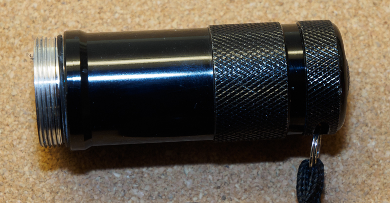
Remove the black O-ring and drill a hole under where it was for the negative lead.
LED Module
I mounted the LEDs and resistors on and inside a piece of cork. I took a sharp knife and cut a segment from the cork that I then trimmed down to a size that would fit securely inside the plexiglass tube. Cut the cork to a length that allows at least the bulbous part of the resistor to fit inside. You can use any number of LEDs you like, but I chose to use six on each baston, so I made six holes in a circle directly through the cork and made sure they were just large enough to hold a resistor each. One more hole is needed for a negative lead from the flashlight body. The seventh hole is on the same circle as the LED/resistor mounting holes. I used a black marker to make sure I knew which hole was for that lead.
Note that one of the LED leads is longer than the other. The lead that has to plug to the positive lead from the power source is longer. This is easy to remember if you remember that the two lines that form a plus sign put together are longer than the single line in a minus sign. Each LED needs to be soldered to a resistor. Some cheap flashlights skip this and use just one resistor for a whole bunch of LEDs and they can usually get away with this, but if you are building something yourself, you might as well do it right? The LED will work with the resistor on either side, but for this particular build, you have to attach the resistor to the longer (positive) lead of the LED. This is because the negative lead from the power pack goes through the cork to the same side as the LEDs and the positive pushes against the base of the cork on the other side.
In order to pick a suitable resistance, you need to know the maximum voltage of your power source and the voltage drop across the LED. In my case, the maximum voltage from three AAA alkaline batteries can be up to 3 x 1.65V = 4.95V. The voltage will quickly drop to about 4.5V, but it’s better to design for the maximum. If I chose to use NiMH rechargeables only, I would calculate the resistor for 3 x 1.3 = 3.9V instead. The resistor is there in order to limit the current to the LED. If the resistor value is too low, the LED will burn brighter, but it might also burn out completely. If the resistance is higher, the LED will be dimmer and will use less power as well.
If you make a test circuit with a power source, some resistor (say 300-500Ω) and a 5V power supply, you can use a multimeter to measure the actual voltage across the LED. In my case, the voltage drop was 3.0V. The voltage drop across the resistor is 4.95V – 3.0V = 1.95V. Resistance is the voltage divided by the current. We want the current to be 20mA (0.02A), so the resistance is 1.95V / 0.02A = 97.5Ω, which is 100Ω when you round it up to a size that you can actually buy.
I came up with a little trick for soldering resistors to LEDs that makes the job a whole lot easier and doesn’t require super steady hands or special tools other than a pin or small paper clip. Starting from around the middle of the bare lead on one side of the resistor, wrap it tightly into a coil around the pin and then carefully bend it a bit so that the spiral is a natural extension of the resistor (see photo). Push the long (positive) lead from the LED through the coil and make a 90° bend on the short (negative) lead away from the positive lead. Use the soldering to apply a bit of solder on the spiral and you should have an extremely solid solder joint as a result. You can test the LEDs at this point by connecting them to a 5V power source – just remember to get the polarity right. Once you start soldering them all together, it’s harder to replace an individual broken LED.
-
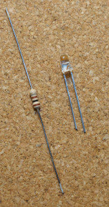
- Step 1: LED & Resistor.
-

- Step 2: Make a coil shape.
-

- Step 3: Solder coil onto LED lead and cut off excess.
The resistor goes in the tunnel through the cork and the negative lead points towards the circle of LEDs and meets the other negative leads right in the middle. Feel free to cut the negative lead to a suitable length or simply make another bend to form a neat little crown in the middle. The crown is where you also solder the wire that will be soldered to the body of the flashlight and that goes through the seventh hole in the cork.
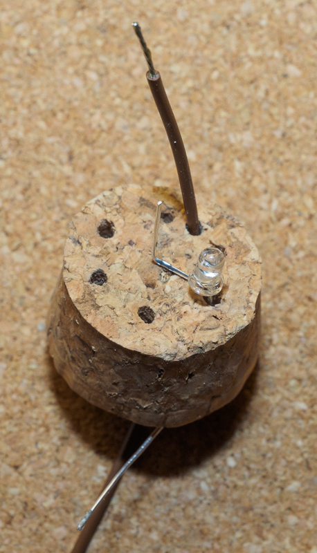
First LED in place along with negative lead. Holes for 5 more LEDs.
On the hilt side of the cork, the lead from the resistor is also bent towards the center on that side. If the lead is really long and goes way past the middle, it can be trimmed a bit shorter than then pushed inside the cork with a 90° bend. Once all the positive leads from the resistors are neatly in the middle, apply a bit of solder to connect them all and make a small bump that acts as a contact point with the positive pole from the battery pack.

View from the battery compartment side, showing the leads from the LEDs meeting in the middle and the negative wire passing through the cork.
At this point, you can test the LEDs by pushing the cork against the flashlight body. Remember that the flashlight has a toggle switch at the butt, so you may have to turn that on if it was off.
Finishing Touches
The end cap at the tip of the weapon is also cork. I cut the cork to a size that makes a nice end cap and used double sided tape to attach the small mirror it. I added some epoxy later on when I had epoxy mixed to glue the hilt to the “blade”. I covered the plexiglass tube with a couple of layers of plastic wrap to make the surface look a bit more textured. I then cut three 7 cm segments (about 3″) of heat shrink tube and one 4 cm segment (1.6″). I perforated two of the longer segments a bit to decorate them a little. The two segments in the middle are not glued down, so they are easy to replace. (January 16th update: I ordered a 3D printer, so one application would be to make 3D-printed versions with detailed graphics.) Heat shrink tube is commonly used in electronics to insulate or wrap cables neatly. In this case, the rather large 35mm diameter tube fits nicely over the tube. I used an incandescent spotlight (60W, I think) to heat the tube, but you can use a hair dryer or the soldering iron or anything else that allows you to controllably warm the tube to over 125°C.
I mixed a bit of epoxy glue. The glue was first used to secure the mirror to the end cap and the end cap to the tube. Then, the LED module and the wire from the hilt to the module were glued in place. Last, the hilt and blade parts are glued together. They fit very neatly together and the threads on the flashlight ensure that the glue will hold really well. I then quickly applied the heat shrink tube over the tip and the joint between the hilt and blade. I used 5 minute epoxy, so all this needs to be done rather quickly. It’s probably better to work on one baston at a time.
AAA alkaline batteries have a typical capacity of 860-1200 mAh. Driving 6 LEDs at 20mA each is a total of 120mA, so battery life with alkalines is 7-10 hours of continuous use and that’s about how long my first set of batteries lasted. The LEDs will dim somewhat towards the end as the voltage drops and then at some point they will not light up at all.

Batons with power off.

Batons with power on.
Even though this was a relatively simple and quick build, these props were very popular among my friends at the Halloween party. Possible improvements would be a brightness control and a sound output of some kind. The tube is large enough to fit an Adafruit trinket and the 3.3V version would work well with three batteries in the flashlight. Unlike with the Widow’s Bites though, I would probably prefer to drive the LEDs using transistors rather than directly from the microcontroller. This is because you want the weapon to glow rather brightly and the I/O ports only output up to 20mA per port.
Speaking of the Widow’s Bites: stay tuned for the next part of this series…

Halloween version of my costume. Flash photos tend to wash out the glow a lot unless a long exposure time is used. This photo was taken without flash.