The Widow’s Bites are covered in three articles: physical prop, electronics and software.
The Widow’s Bites in the 2012 Avengers are relatively simple-looking bracers that use electricity to stun a target. If you look at the Chitauri fight scene footage, you can see some sort of stingers in the gloves that deliver the charge. However, these are absent in all the poster art that I’ve seen and I was using the posters as reference, so my design doesn’t incorporate the stingers. The modules/pods on the bracer are probably some kind of battery or capacitor that generates the discharge. When they are active, the two shiny bands on each pod light up in blue.
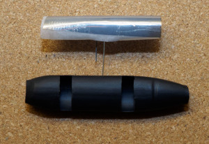
Each bracer I made consists of twelve pods. Most Black Widow costumes seem to make these pods either out of inexpensive costume shop bullet belts or mold them out of solid rubber/silicone. To be honest, I considered the costume shop bullets a last resort as I didn’t think they looked all that convincing. I spent a few days trying to figure out how to make the modules before I came up with an idea. I used heat shrink tube to make a hollow pod, so that I could actually build an LED or two inside and make it glow. I didn’t have a mold at that point, so I just took a bit of tube I had and shaped it using heat alone. It didn’t look exactly right, but it was definitely strong enough and looked quite promising already.
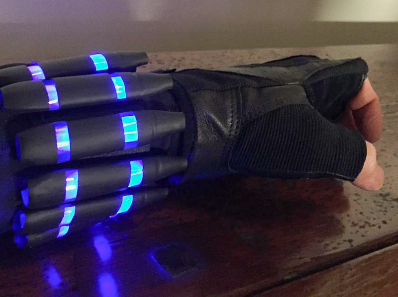
Sneak closeup preview of the assembled widow’s bite bracer & glove.
Module Covers
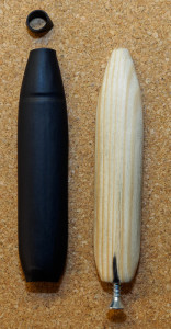
I needed a mold inside the tube to get the right shape, so I took a piece of wood and started whittling. I wanted a tight fit over the 12mm diameter tube, so I was constantly checking the fit. The finished mold is 76mm x 31mm x 10 mm. There are twelve pods on each bracer, so I the minimum amount of shrink tube is nearly two meters with very little room for error. Since the tube is cheap, I recommend getting at least 4 meters. Speaking of cheap though, while the DX tube was great for this application, it does seem a tiny bit thinner than the stuff I have seen at local stores here. You could also buy tube that shrinks to an even smaller size to make the tips sharper.
After making one or two pods, I attached a small screw to the back of the wooden mold to make it easier to pull the tube off. Here’s how I mass-produced the pods:
- I cut the heat shrink tube into segments of the right size. The tube shrinks slightly length-wise, so it’s better to make the segments a bit long rather than too short.
- I inserted a tube on the mold and heated up the tip of the pod shape to shrink it down to size, making sure the groove became clearly visible.
- I then wiggled the mold out of the tube a tiny bit to make sure the front was loose and then pushed it back in again.
- Shrinking the back end of the tube over the pod makes it impossible to remove the tube without cutting it, so there’s a cut under each pod extending from the back of the pod towards the middle. This cut allows you to pull the tube off the mold and start with the next one.
It might actually be a good idea to add some indentations on the mold to show where the glowing windows on the pods should be cut, but I just cut them all manually using a reference pod that I cut.
-
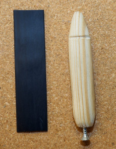
- Heat shrink tube and wooden mold
-
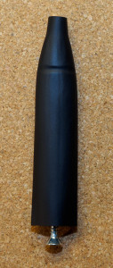
- Tip has been shrunk to size. The mold is still inside, but this is a good time to make sure the tip comes loose.
-
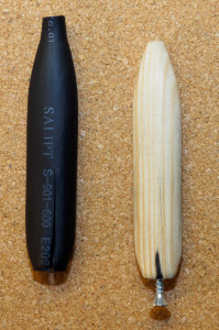
- Tube has been shrunk to shape and the bottom has been cut open so that the mold could be removed.
-
- Top view. If the tube was slighty too long, it can easily be trimmed to size from the ends.
The pod covers will shrink out of shape if heated, so they need to be kept safely stored away while working with a soldering iron or hot glue gun.
Internal Pod Structure
I spent quite some time experimenting with how to build the inside of the pod. The design I chose takes a bit of effort to build, but can essentially made from LEDs, cheap scrap material and clear tape. I used a sheet of translucent packing foam as the base, cutting it into strips that would easily fit inside the pod. The LED caps are pointing towards the tip with the positive (longer) lead in front. The longer leg is bent at a 90° angle quite close to the LED and the shorter leg a bit further away from the LED. The foam base helps prevent the contacts from shorting, but I also added a tiny bit of small diameter shrink tube to one leg on of each LED as insulation. Hot glue would probably work even better.
I used a rectangular piece of baking paper as a diffuser and on top of that, a similar size piece from an antistatic bag to give the pod windows a metallic blue color when the LED wasn’t lit up. Bits of clear tape hold everything in place around the foam and LED. It’s a good idea to test the LEDs with a resistor and power supply before soldering anything.
-
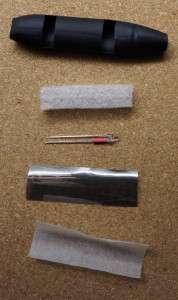
- Pod Assembly 1
-
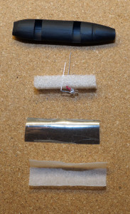
- Pod Assembly 2
-
- Pod Assembly 3
-

- Pod Assembly 4
Outer Bracer
Instead of a circuit board, the LED modules are mounted on 5 cm wide loop (soft) side velcro. The pods are on the smooth side and the resistors, wires and CPU are on the fluffy side. I used a mini drill to make holes for the LED leads and to weave a ground wire near the back end of the velcro. I originally intended the battery pack to be hidden inside the bracer and while it is relatively flat, I ended up mounting the first set of pods slightly too tightly on the velcro. I guess I wasn’t accounting for all the layers between my bare wrist and the top velcro. In addition to the suit sleeve, there’s a hook side velcro as well. The battery pack actually looks like it belongs on the bracer and the slight discontinuity in the pods hasn’t bothered me at all.
Outer and inner bracers with red circles to indicate drilled holes.
The pods are held in place by the LED leads and a bit of heavy duty double sided tape at the front and back. The pod cover slit is taped up and the pods are taped in place as the very last thing of the build. You want to be able to slide the covers on and off easily while you are testing. Once everything works perfectly, you can lock them in place.
Inner Bracer
The inner band goes around the wrist and has some elastic for good fit & comfort. It consist of 12.5 cm (5″) of hook side velcro sewn onto 10 cm (4″) of elastic and 2cm (0.8″) of loop velcro.
Making 24 pods and wiring them all up takes quite a lot of time. It took me about three evenings to get the second bracer built from scratch. The first one took a lot longer, because I was spending more time designing and experimenting than actually building.
Completed Outer & Inner Bracer
Parts:
- 2 meters of Ø12mm heat shrink tube.
- 24+ bright blue 3mm LEDs (3.0V – 3.2V, 20mA)
- 24+ 500Ω resistors
- A small sheet of translucent white foam
- Some baking paper
- A medium-sized antistatic bag or several small ones
- Plenty of wire
- 50 mm wide velcro (hook and loop) – one meter is probably enough
- 50 mm wide elastic fabric band
- two dual CR2032 battery holders
- Two Adafruit Trinkets, 5V version
- Two microswitches
- Black velcro stickers
- Solder & solder wick
Recommended tools:
- Sewing machine
- Soldering iron (15W sharp tip was great again)
- Dremel-like drill or some other way to quickly make nice holes in velcro
- Digital multimeter
- Wire cutters
- Wire peeling tool
- Small pliers
Front view of completed bracer.