In this second article of the Widow’s Bite build, I’ll describe how the electronics were designed and built.
I used a 5V version of the Adafruit Trinket, which is a lightweight/low power version of the popular Arduino platform. The bracers can be built without the microcontroller, but adding the microcontroller only requires a few more wires and a tiny bit more soldering. The Trinkets are just ~$7 each and they open up a lot of possibilities, so there’s really no excuse to leave them out. If you build the circuit without a microcontroller, one adjustable resistor might be a good idea for controlling the brightness and power.
I built a mockup version of the circuit using just four LEDs and a 3.3V Trinket. The circuit is powered from the USB port on the Trinket. The 5V trinket will work too. I soldered headers on the Trinket to mount it on the breadboard, but it’s possible to do the mounting without soldering. The advantage of the mockup/test rig was that I could start working on the software several days before I had the bracer finished. The software is described in the next article.
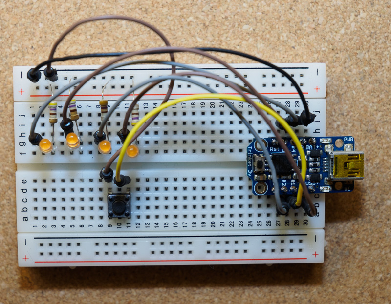
Bracer circuit on a breadboard, using a 3.3V Trinket.
LED Control Wiring
The outer bracer structure was shown in the previous article. To recap, the velcro has holes for the LED leads and holes for securing a ground wire near the back of the bracer. The photos show how the ground wires weaves through the velcro.
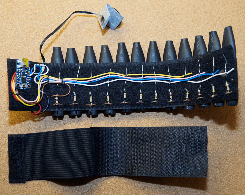
Completed Outer & Inner Bracer
I pulled the LED wires through the holes in the velcro and bent the negative (shorter) lead towards the ground wire and the positive (longer) lead toward the front. I made small spirals on the resistors to make the soldering to the negative LED lead really easy (see part 5). To connect the other end of the resistor the the ground wire, I used a sharp knife to peel off some of the insulation on the wire and then pushed a sewing pin through the braid to make a hole large enough for the resistor lead. Doing this makes the soldering really easy.
Four control wires are used for the positive LED leads. Each wire is connected to three LEDs, so if you number the LEDs from 1-12, then the first wire will control LEDs 1, 5 and 9. The second one is 2-6-10, third is 3-7-11 and the last one is 4-8-12. There’s no way to control individual LEDs this way, but some nice animations are still possible even though you only have four pixels to work with. I used a black marker to mark the places where I needed to solder the LED wires and then peeled & made holes in the braid in those places. I used a sort of over/under weaving technique to secure the wires and LED leads. Soldering can be done as you do the weaving or it left until everything is in place.
I intentionally reversed the order of the groups for left and right so that if one side has an animation spinning clockwise, the other one would be going counter-clockwise. It’s a change that is actually very easy to do in software as well, so it doesn’t matter much which GPIO pins you pick if you know how change the program.
Glove switches
The Adafruit Trinket has five general purpose I/O pins. My design uses four of them for the LEDs, which leaves just one to use an an input to control the bracer. I took a low profile microswitch, a bit of bendable vinyl and some velcro to craft a switch that can be attached inside the palm of a glove. One wire connects to the ground and the other goes to the remaining I/O pin on the Trinket. There’s a square hole in the vinyl for the switch. Once the leads are soldered on, I used epoxy glue to fix the switch to the hole.
-
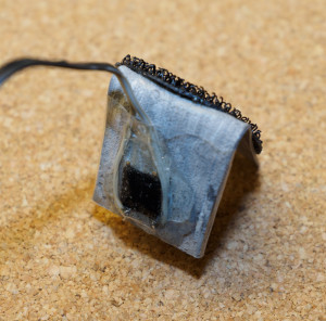
- Soldered leads with epoxy on top.
-
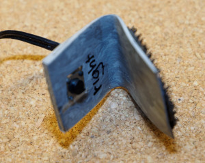
- The microswitch button is visible here.
Power Supply
The power module is just a battery pack for two CR2032 lithium batteries. I like the battery pack because it has a built-in on/off switch and it’s really slim. I used some velcro stickers to attach it. The red wire solders into the BAT+ contact on the Trinket and the black wire goes into the ground wire, which is finally attached to the Trinket’s GND contact.
Battery life seems excellent, but if you want a rechargeable option, it’s possible to build the bracers using something a lithium polymer battery. Just be aware that you then need to use the 3.3V version of the trinket, the resistor values would need to be a whole lot lower and the LEDs must be verified to be close to 3.0V. There’s just 0.3V margin for the resistor to control the current, so in order to get 4mA per LED max, the resistance would be 0.3V/0.004A = 75Ω. For my build, I’m assuming a 6V power supply, which the 5V trinket regulates to 5.0V, so the resistors are 500Ω for 4mA per LED. I estimate battery life to be about 10-12 hours, but it will depend a lot on the brand of batteries used, the software loaded on the microcontroller and how much you run the LEDs at full brightness.
The Trinket will always draw 6mA of current, so even though you can turn off all the LEDs using a glove switch command, it’s a good idea to use the battery pack power switch when the bracer is not in use. Upon powering up, the Trinket will first try to connect with USB and because the I/O pins are shared between USB and our LEDs, this will cause some of the LEDs on the bracer to light up for a few seconds before our own software takes control.
Connect the Dots
The wires I used were all pre-cut and different colors, so the photos should make it pretty easy to see where they all go. I decided on where to place the Trinket and how to route the wires there. I then cut the wires to suitable lengths, tinned the leads and soldered them on to the Trinket. At this point, the bracer was ready for testing. As usual, there were moments of confusion and panic as nothing seemed to work. One of the batteries in the pack was dead. A new set of batteries helped a bit, but the bracer was unresponsive to the commands from the glove switch. At first I thought that maybe the coin batteries simply weren’t powerful enough for this, but plugging the bracer to USB didn’t help. I desoldered the button from GPIO 0 and moved it to GPIO 1 and that fixed the problem. GPIO 0 was working well as an output.

This is how the trinket is wired on one of my bracers.
I decided to use the same design on both bracers…except that when I was soldering the second bracer, I accidentally used the orignal pin choices and ended up with another bracer with a dead palm switch. At this point, instead of just changing the wiring again, I tried to figure out why the switch didn’t work with GPIO 0. Soldering these leads the first time is easy…doing so the second time is harder – try to get them right the first time unless you have a good desoldering station. I guessed that it had to something to do with the red built-in LED on GPIO 0, so I just took a knife and cut it out. The switch started working. My first bracer uses GPIO 1 as the switch and the second one uses GPIO 0 and I need to make a tiny software configuration change based on which side I’m programming.
Due to voltage differences, GPIO 0 works great as the switch input using the 3.3V breadboard mockup, but not at all when conneted to the 5V version of the bracer. The red LED is actually very nice to have for debugging on the Trinket when you are programming it, but once it’s in the bracer, all it does is consume a lot of power. It’s just best to cut both LEDs off the Trinket. The built-in LEDs are surface mounted next to the USB connector.
I used needle and thread to secure all the wires and the trinket to the velcro. There are quite a few exposed contacts, so I think there’s a risk to create some shorts and drain the battery if you wear the outer bracer on bare skin. It’s best to always use the inner bracer with the bracer. The “pods” aren’t waterproof anyway, so it doesn’t seem worth insulating any of the other electronics either.

Wiring without annotations.